Abrasive or corrosive products
Industrial water
Sea water
Low temperature water vapor
AR/CN
-35°C+90°C
The M series is available in a standard design but can also be produced in new shapes, lengths, and double-wave configurations to meet the most demanding specifications. The M series is also available in DN > 2200. Contact us for details!
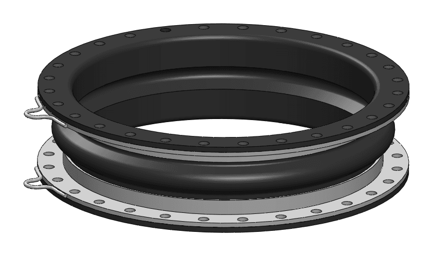
Different drilling diameters and templates are available for this series. The corresponding displacement capacities are shown in the table below.
Maximum permissible displacements (maximum values do not apply simultaneously)
| TYPE | DN | Nominal diameter | Ln (mm) | Ln (mm) | Ln (mm) | PN 2.5—PN 6/ PN 10/CL150 | PS (bar) | Vacuum ring required if vacuum greater than | Axial Compression Ln-Lc (mm) | Axial Elongation Le-Ln (mm) | Lateral Shearing R (mm) | Angular Angle α° (degree) | Reaction force (kdaN) P | Reaction force (kdaN) V | Approximate mass (kg) |
|---|---|---|---|---|---|---|---|---|---|---|---|---|---|---|---|
| MD 40 | 500 | 20 | 225 | 250 | X | 4 | 100% | 20 | 0 | 30 | 2.3 | 1.7 | 2.3 | 42 | |
| MD 40 | 600 | 24 | 225 | 250 | X | 4 | 100% | 20 | 0 | 30 | 1.9 | 1.4 | 3.2 | 53 | |
| MD 40 | 800 | 32 | 250 | X | 4 | 100% | 20 | 0 | 30 | 1.4 | 1.1 | 5.6 | 82 | ||
| MD 40 | 1000 | 40 | 250 | 300 | X | 4 | 100% | 20 | 0 | 30 | 1.1 | 0.9 | 8.5 | 111 | |
| MD 40 | 1200 | 48 | 300 | X | 4 | 100% | 20 | 0 | 30 | 0.9 | 0.7 | 12.1 | 179 | ||
| MD 40 | 1400 | 56 | 300 | X | 4 | 100% | 20 | 0 | 30 | 0.8 | 0.6 | 16.4 | 225 | ||
| MD 40 | 1600 | 64 | 300 | X | 4 | 100% | 25 | 0 | 30 | 0.9 | 0.5 | 21.2 | 345 | ||
| MD 40 | 1800 | 72 | 300 | X | 4 | 100% | 25 | 0 | 30 | 0.8 | 0.5 | 26.7 | 392 | ||
| MD 40 | 2000 | 80 | 300 | X | 4 | 100% | 25 | 0 | 30 | 0.7 | 0.4 | 32.9 | 450 | ||
| MD 40 | 2200 | 88 | 300 | X | 4 | 100% | 25 | 0 | 30 | 0.7 | 0.4 | 39.6 | 525 | ||
| MS 50 | 500 | 20 | 250 | X | 6 | 0% | 20 | 15 | 30 | 4 | - | 2.4 | 49 | ||
| MS 50 | 600 | 24 | 250 | X | 6 | 0% | 20 | 15 | 30 | 3.3 | - | 3.4 | 60 | ||
| MS 50 | 800 | 32 | 250 | X | 6 | 0% | 20 | 15 | 30 | 2.5 | - | 5.8 | 92 | ||
| MS 50 | 1000 | 40 | 250 | 300 | X | 6 | 0% | 20 | 15 | 30 | 2 | - | 8.8 | 122 | |
| MS 50 | 1200 | 48 | 300 | X | 6 | 0% | 20 | 15 | 30 | 1.7 | - | 12.4 | 200 | ||
| MS 50 | 1400 | 56 | 300 | X | 6 | 0% | 20 | 15 | 30 | 1.4 | - | 16.4 | 251 | ||
| MS 50 | 1600 | 64 | 300 | X | 6 | 0% | 20 | 15 | 30 | 1.2 | - | 21.5 | 391 | ||
| MS 50 | 1800 | 72 | 300 | X | 6 | 0% | 20 | 15 | 30 | 1.1 | - | 27 | 438 | ||
| MS 50 | 2000 | 80 | 300 | X | 6 | 0% | 20 | 15 | 30 | 1 | - | 33.1 | 500 | ||
| MS 50 | 2200 | 88 | 300 | X | 6 | 0% | 20 | 15 | 30 | 0.9 | - | 39.9 | 580 | ||
| MA 60 | 500 | 20 | 250 | 300 | X | 8 | 0% | 30 | 30 | 30 | 6.8 | - | 2.6 | 54 | |
| MA 60 | 600 | 24 | 250 | 300 | X | 8 | 0% | 30 | 30 | 30 | 5.7 | - | 3.6 | 68 | |
| MA 60 | 800 | 32 | 250 | 300 | X | 8 | 0% | 30 | 30 | 30 | 4.3 | - | 6.1 | 98 | |
| MA 60 | 1000 | 40 | 250 | 300 | X | 8 | 0% | 30 | 30 | 30 | 3.4 | - | 9.1 | 135 | |
| MA 60 | 1200 | 48 | 300 | X | 8 | 0% | 30 | 30 | 30 | 2.9 | - | 12.8 | 215 | ||
| MA 60 | 1400 | 56 | 300 | X | 8 | 0% | 30 | 30 | 30 | 2.4 | - | 17.2 | 273 | ||
| MA 60 | 1600 | 64 | 300 | X | 8 | 0% | 30 | 30 | 30 | 2.1 | - | 22.1 | 405 | ||
| MA 60 | 1800 | 72 | 300 | X | 8 | 0% | 30 | 30 | 30 | 1.9 | - | 27.7 | 454 | ||
| MA 60 | 2000 | 80 | 300 | X | 8 | 0% | 30 | 30 | 30 | 1.7 | - | 33.9 | 514 | ||
| MA 60 | 2200 | 88 | 300 | X | 8 | 0% | 30 | 30 | 30 | 1.6 | - | 40.7 | 617 | ||
| MB 60 | 500 | 20 | 250 | 300 | X | 8 | 100% | 30 | 10 | 30 | 4.6 | 4.6 | 2.6 | 61 | |
| MB 60 | 600 | 24 | 250 | 300 | X | 8 | 100% | 30 | 10 | 30 | 3.8 | 3.8 | 3.6 | 77 | |
| MB 60 | 800 | 32 | 250 | 300 | X | 8 | 100% | 30 | 10 | 30 | 2.9 | 2.9 | 6.1 | 109 | |
| MB 60 | 1000 | 40 | 250 | 300 | X | 8 | 100% | 30 | 10 | 30 | 2.3 | 2.3 | 9.1 | 149 | |
| MB 60 | 1200 | 48 | 300 | X | 8 | 100% | 30 | 10 | 30 | 1.9 | 1.9 | 12.8 | 232 | ||
| MB 60 | 1400 | 56 | 300 | X | 8 | 100% | 30 | 10 | 30 | 1.6 | 1.6 | 17.2 | 290 | ||
| MB 60 | 1600 | 64 | 300 | X | 8 | 100% | 30 | 10 | 30 | 1.4 | 1.4 | 22.1 | 426 | ||
| MB 60 | 1800 | 72 | 300 | X | 8 | 100% | 30 | 10 | 30 | 1.3 | 1.3 | 27.7 | 477 | ||
| MB 60 | 2000 | 80 | 300 | X | 8 | 100% | 30 | 10 | 30 | 1.1 | 1.1 | 33.9 | 550 | ||
| MB 60 | 2200 | 88 | 300 | X | 8 | 100% | 30 | 10 | 30 | 1 | 1 | 40.7 | 645 |
Notes:
(1) Within the limit of the nominal pressure of the connection template used
(2) Counter flanges in 1 part in galvanized steel, bichromated zinc-plated steel, stainless steel.
(*) For other lengths. Contact us to discuss your requirements.
(**) For other connection templates. Contact us to discuss your requirements.
(***) For higher displacement values. Contact us to discuss your requirements.
For all other intermediate diameters and up to DN 2800 mm. Contact us to discuss your requirements.
Determining the quality must take into account the nature of the fluid as well as the operating temperature range. The qualities mentioned below provide an indication of compatibility with various industrial fluids, under positive and negative temperature conditions.


Need technical assistance?

After assembly and/or commissioning/recommissioning of the installation, check the tightening torque every 24 hours for 3 to 5 days. Retighten to the correct torque if necessary.
The most alarming sign of visual wear is cracks or fissures exposing the expansion joint's carcass. Checking the hardness with a durometer is another way to monitor the ageing of the expansion joint.
The repair process is delicate. It is recommended to replace the expansion joint.
The ideal pipe flanges are those with a flat face. Mounting on flanges with a raised face, an annular seal, a push-fit connection, or a collar is not recommended. For push-fit flanges, ensure that the end of the pipe is neither protruding nor recessed from the mounting face and that there are no visible welds.