Abrasive or corrosive products
Industrial water
Sea water
Low temperature water vapor
AR/CN
-35°C+90°C
The N series is undeniably the range of expansion joints which, due to its imposing size and large travel, allows it to remain installed for quarters of a century.
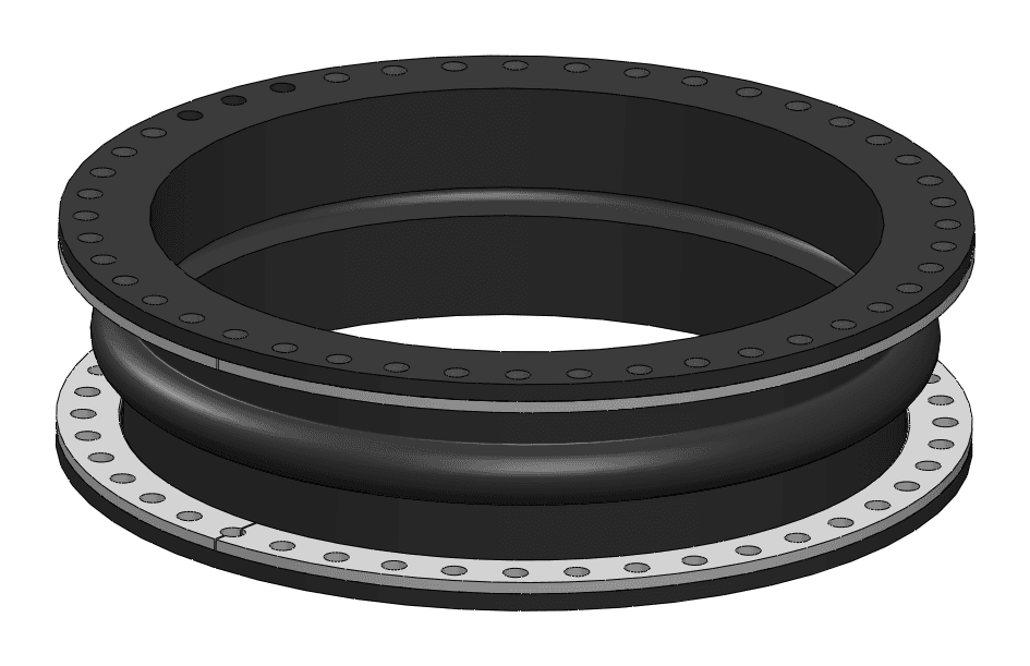
The series is available in several diameters and drilling templates. The corresponding displacement capacities are shown in the following table.
Maximum permissible displacements (maximum values do not apply simultaneously)
| DN | Nominal diameter | Nominal length Ln (mm) | PN 2.5 | PN 6 - PN 10 | PN 16 | Class 150 | PS (bar) | Vacuum ring required if vacuum greater than | Axial Compression Ln-Lc (mm) | Axial Elongation Le-Ln (mm) | Lateral Shearing R (mm) | Angular Angle α° (degree) | Reaction force (kdaN) | Approximate mass (kg) |
|---|---|---|---|---|---|---|---|---|---|---|---|---|---|---|
| 500 | 20 | 300 | X | X | X | 10 | 20% | 40 | 30 | 20 | 6 | 2.5 | 30 | |
| 550 | 22 | 300 | *** | *** | 10 | 20% | 20 | 30 | 15 | 4 | 3 | 40 | ||
| 600 | 24 | 300 | X | X | X | 10 | 20% | 40 | 40 | 20 | 7 | 3.8 | 43 | |
| 700 | 28 | 300 | X | X | X | 10 | 20% | 40 | 40 | 20 | 6 | 4.9 | 44 | |
| 750 | 30 | 300 | *** | *** | *** | 10 | 20% | 20 | 20 | 15 | 3 | 5.3 | 60 | |
| 800 | 32 | 400 | X | X | X | 10 | 20% | 40 | 40 | 20 | 5 | 6.3 | 67 | |
| 850 | 34 | 400 | *** | *** | *** | 10 | 20% | 40 | 40 | 20 | 5 | 7 | 70 | |
| 900 | 36 | 400 | X | X | X | 10 | 20% | 40 | 40 | 20 | 5 | 8.8 | 80 | |
| 1000 | 40 | 400 | X | X | 10 | 20% | 40 | 40 | 20 | 4 | 9.4 | 84 | ||
| 1100 | 44 | 400 | *** | *** | *** | 6 | 20% | 40 | 30 | 20 | 3 | 10.7 | 100 | |
| 1200 | 48 | 400 | X | X | X | 6 | 20% | 40 | 40 | 20 | 3 | 13.2 | 120 | |
| 1250 | 50 | 400 | *** | *** | 6 | 10% | 40 | 40 | 20 | 3 | 14.2 | 115 | ||
| 1300 | 52 | 400 | *** | 6 | 10% | 20 | 20 | 15 | 1.5 | 14.8 | 115 | |||
| 1400 | 56 | 400 | X | 6 | 10% | 40 | 40 | 20 | 3 | 17.6 | 150 | |||
| 1500 | 60 | 400 | *** | 6 | 10% | 20 | 20 | 15 | 1.5 | 20 | 170 | |||
| 1600 | 64 | 400 | X | 6 | 10% | 40 | 30 | 20 | 2 | 22.4 | 183 | |||
| 1700 | 68 | 400 | *** | 6 | 10% | 40 | 30 | 20 | 1.5 | 25.2 | 215 | |||
| 1800 | 72 | 400 | X | 6 | 10% | 20 | 20 | 15 | 1 | 27.8 | 225 | |||
| 2000 | 80 | 750 | X | 1.5 | 150 | 100 | 50 | 5 | 38.3 | 275 | ||||
| 2200 | 88 | 750 | X | 1.5 | 150 | 150 | 75 | 7 | 48.2 | 400 | ||||
| 2400 | 96 | 400 | X | 4 | 50 | 40 | 20 | 1.5 | 49.6 | 300 | ||||
| 2500 | 100 | 750 | *** | 1.5 | 150 | 100 | 50 | 4 | 56.8 | 450 | ||||
| 2600 | 104 | 750 | X | 1.5 | 150 | 150 | 75 | 6 | 64.4 | 500 | ||||
| 3000 | 120 | 750 | X | 1.3 | 150 | 100 | 50 | 3 | 79.3 | 550 |
Notes:
(***) Non-standard sizes.
(1) Other drillings available (e.g. PN6, PN25, PN40, BS 10D-E). Contact us to discuss your requirements.
(2) For higher working pressure: NS series. Contact us to discuss your requirements.
(3) Within the limit of the nominal pressure of the connection template used.
(4) Expansion joints to be mounted with 2-part counter-flanges in bichromated zinc-plated steel, galvanized steel, stainless steel.
(5) For vacuum work: NV series. Contact us to discuss your requirements.
(6) The vacuum support ring can impact the permissible displacement values of the expansion joint. Contact us to discuss your requirements.
The selection of the appropriate grade must be based on the fluid being used and the operating temperature range. The grades listed below provide an overview of their compatibility with various industrial fluids, for both positive and negative operating temperatures.


Need technical assistance?

The ideal pipe flanges are those with a flat face. Mounting on flanges with a raised face, an annular seal, a push-fit connection, or a collar is not recommended. For push-fit flanges, ensure that the end of the pipe is neither protruding nor recessed from the mounting face and that there are no visible welds.
The bearing faces of the pipe flanges must be wiped clean and free of foreign matter (cement splashes, paint, rust, grease) and of any abnormal deformation. The misalignment between two opposing flange holes must not exceed 3 mm. The flatness of the surface in contact with the expansion joint must not exceed 1.5 mm. The axes of the pipe flanges must be coaxial, with a maximum deviation of Ø 3 mm. The parallelism of the surfaces in contact with the expansion joint must not exceed 2 mm.
The distance between a piece of equipment and an expansion joint must be 1 DN to 1.5 DN.